When we last left Project Why Wait I had just manged to recover from an *ahem* slight miscalculation of rear shock placement. That little snafu necessitated a few steps backward, and a lot of sanding to course correct.
I’d love to say that this update doesn’t include a fair bit of sanding, but I don’t fancy myself a liar. However, it didn’t begin with a lot of sanding. Instead it started with some good of fashion planning and mock-up.
Aside from the suspension, the rear of this chassis had no real mounting systems to speak of. This has been a bit of a double-edged sword. It’s given me the freedom to put things anywhere I want, but to put them anywhere I want requires at least some level of fabrication.
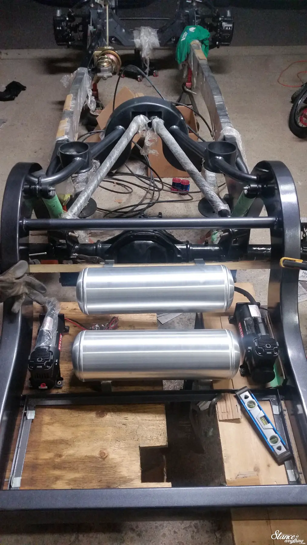
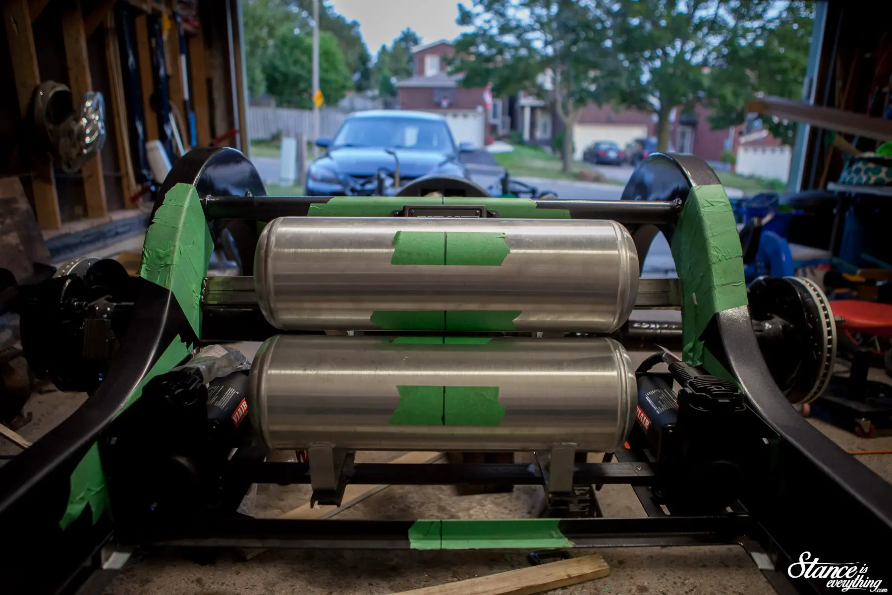
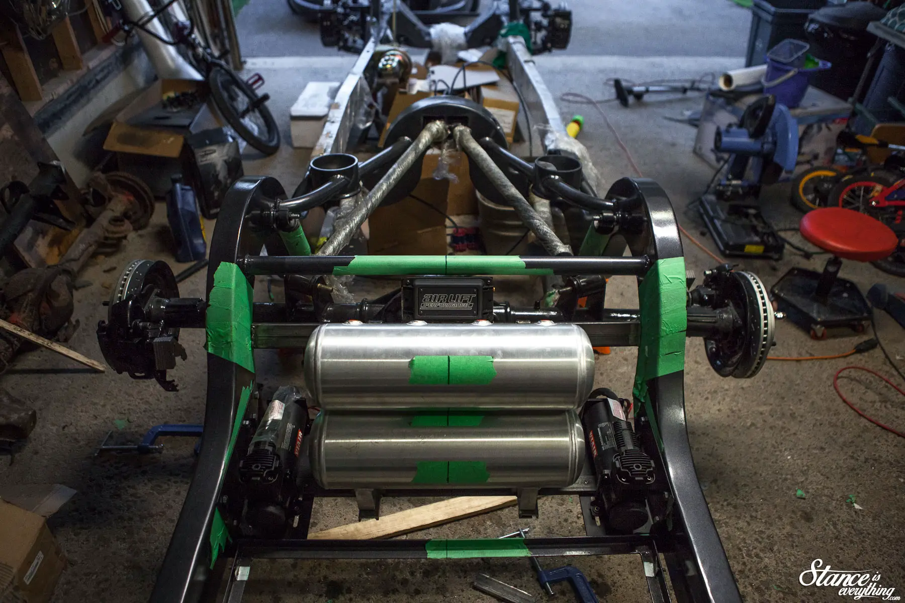
One such system that needed a home, but had no place to go, was my air management. Consisting of two Air Lift Performance 2.5 gallon tanks, two Viair compressors and an Air Lift 3H manifold/ecu, the management makes up one of the larger component sets I needed to find a home for.
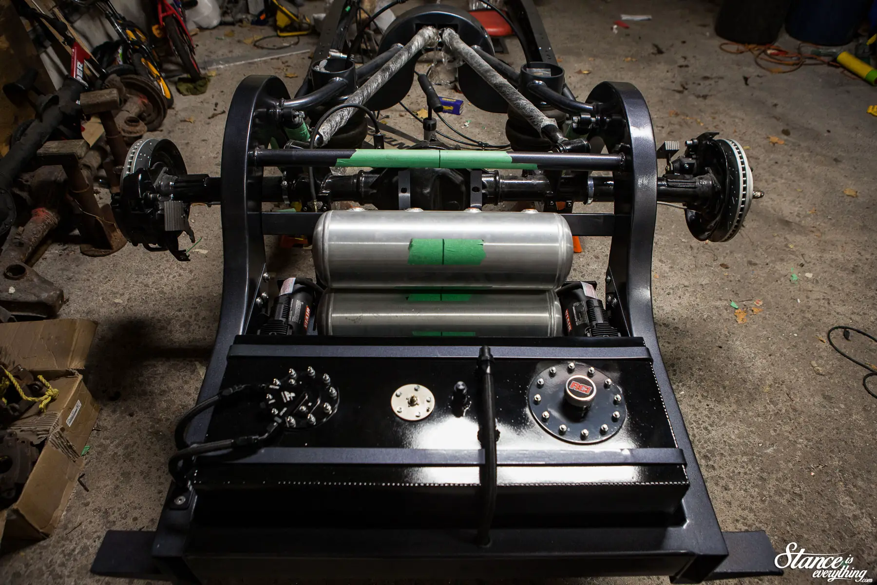
After holding the tanks and compressors in various positions all about the chassis, I settled on a pocket of space between the axle and the fuel cell.
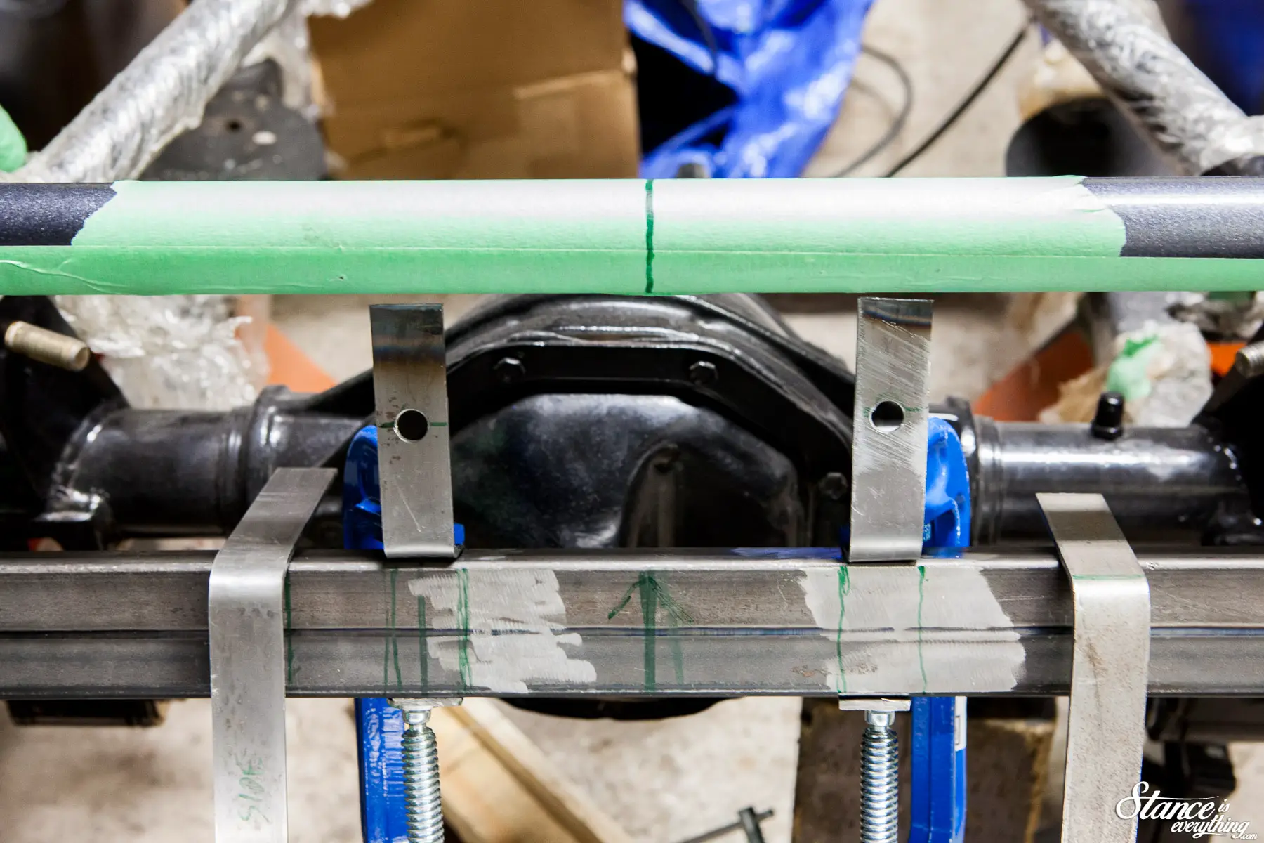
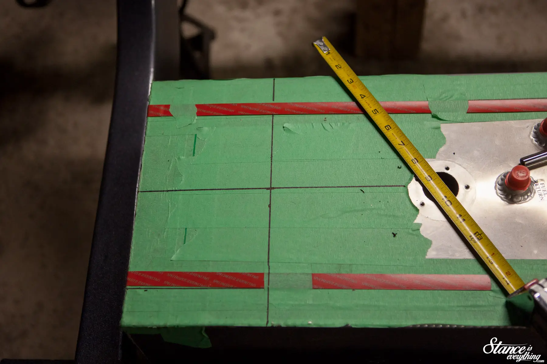
Using green tape –tape which I should buy by the crate at this point– and a sharpie to mark the center lines on the chassis I started with the compressor mounts and lower tank mount.
The compressor mounts are off the shelf Viaair units that I’ve modified for my application by contouring the vertical edge to match my frame rail, and relocating one of the gussets.
New mounting holes were drilled next, and the frame was tapped to accept bolts.
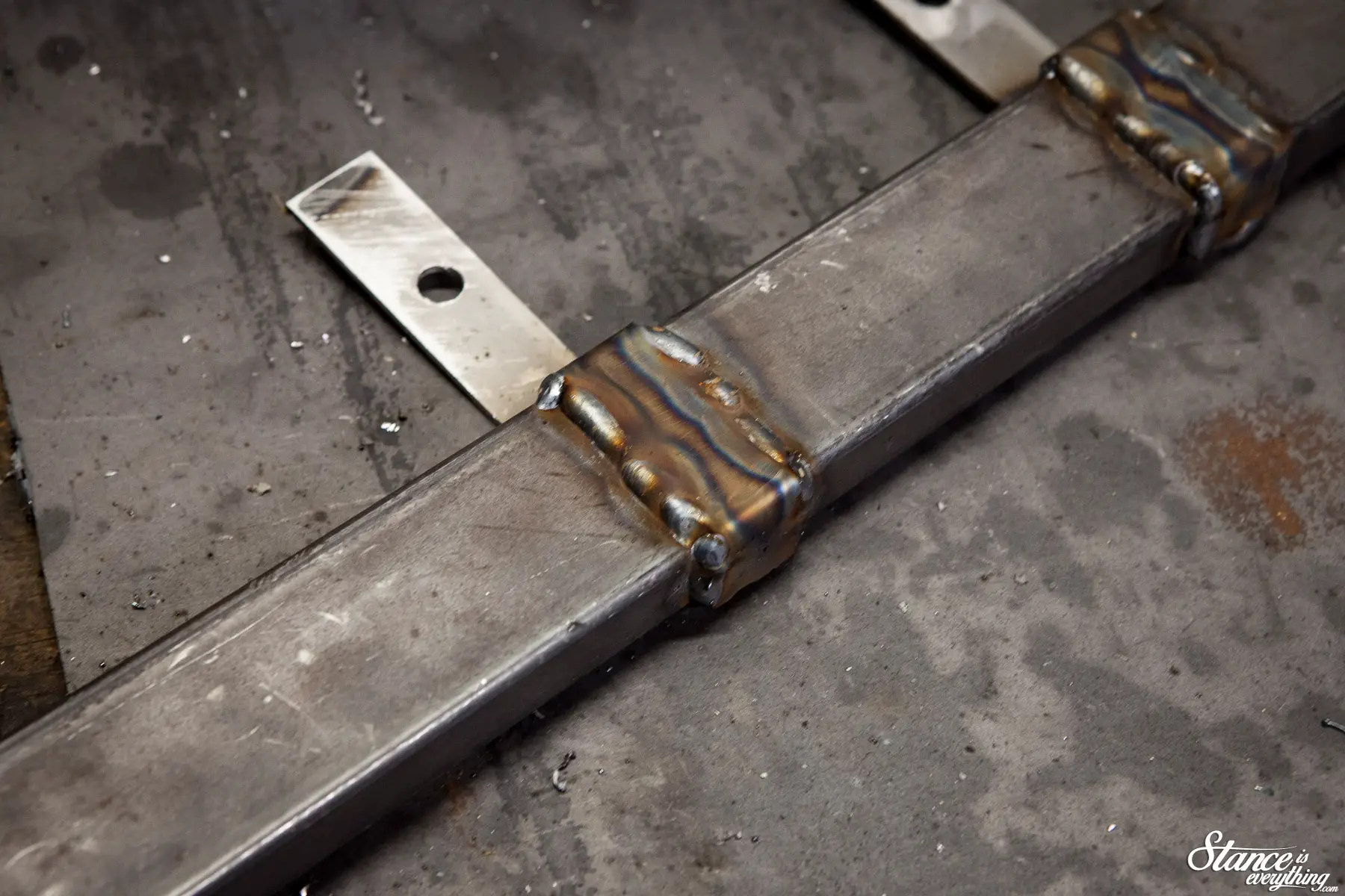
For the tank mount I ran a piece of C-channel from one compressor mount to the other. Bolts are welded into the recess of the C-channel (three per side) to create a hidden mounting system when viewed from the top down.
Connecting the two compressor mounts together in this way added significant rigidity to the mounting system. The tank shouldn’t bobble around much and neither will the compressors.
Mounting the upper tank proved a bit more challenging because there was nothing for me to really mount the cross member to.
Had the chassis not been coated and painted I could have easily zapped one in, but with the paint hardly dry from the last update I wasn’t to keen on this idea.
After a bit of thought I devised a pretty simple mounting solution.
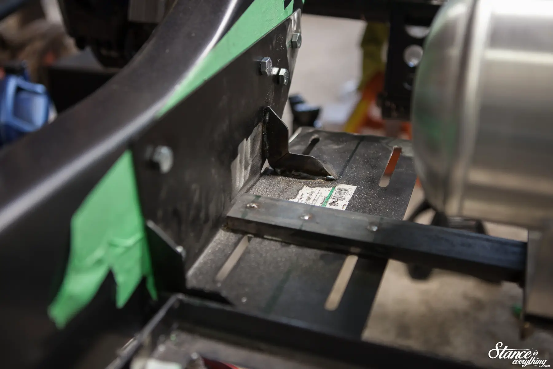
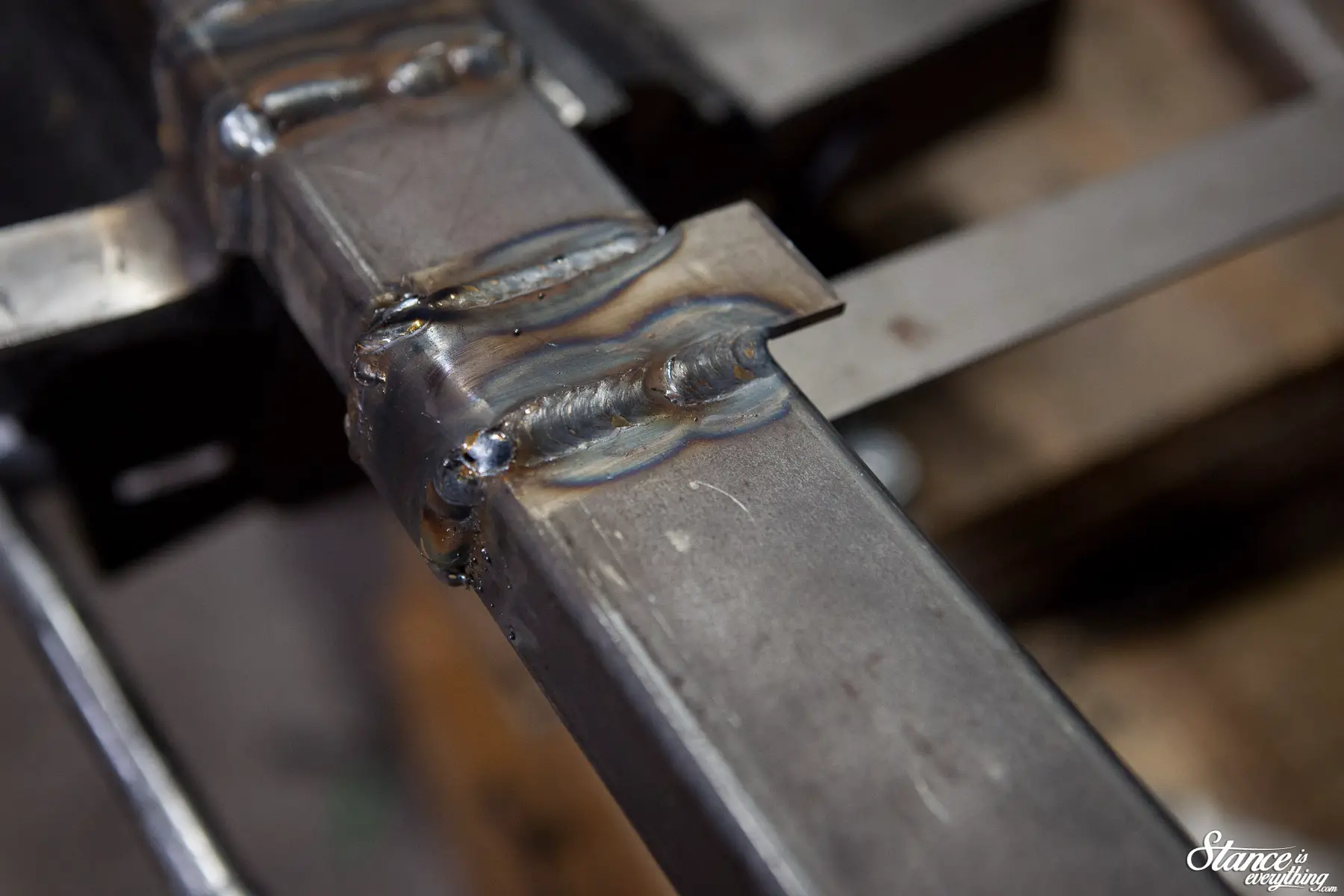
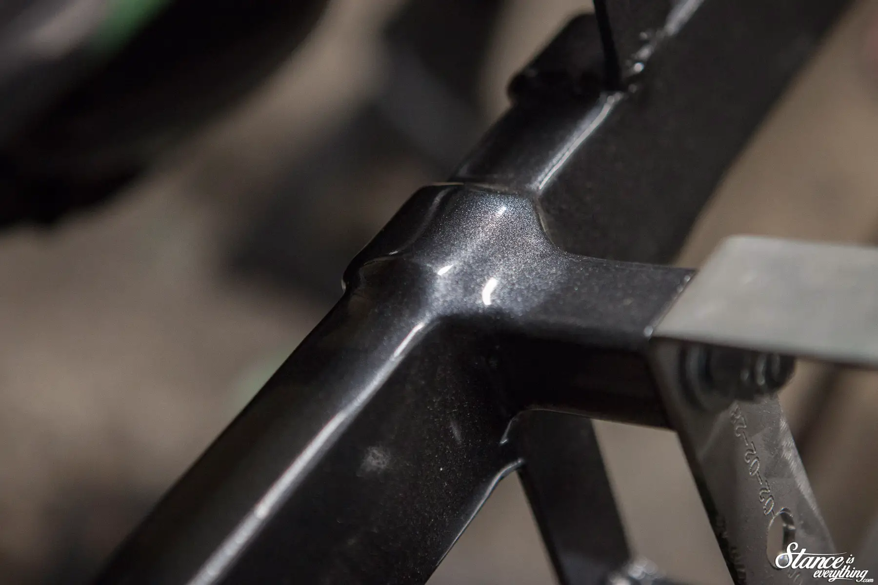
Yes, that is, a piece of angle iron tack welded to the end of a piece of box steel. I wanted a nice uniform 90 around the frame rail and this was the best way I could achieve that with the tools I had available.
That piece above was a quick functional prototype of the idea. I beat it all to hell to ensure that the mount wouldn’t fall off as I went down the road.
To give things a bit more of a mounting surface I welded an additional piece of flat stock to the end of the angle iron for a larger mounting surface to the frame.
It was all welded completely before my tap and die came out once more to mount the new cross member.
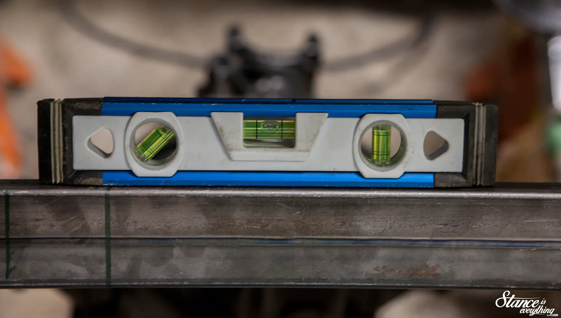
Along the way I made sure to check, re-check, and check again that everything was level before proceeding to the next step, test fitting the manifold and upper tank.
This is where I realized I hadn’t accounted for placement of the air lines and wiring harness going into the manifold.
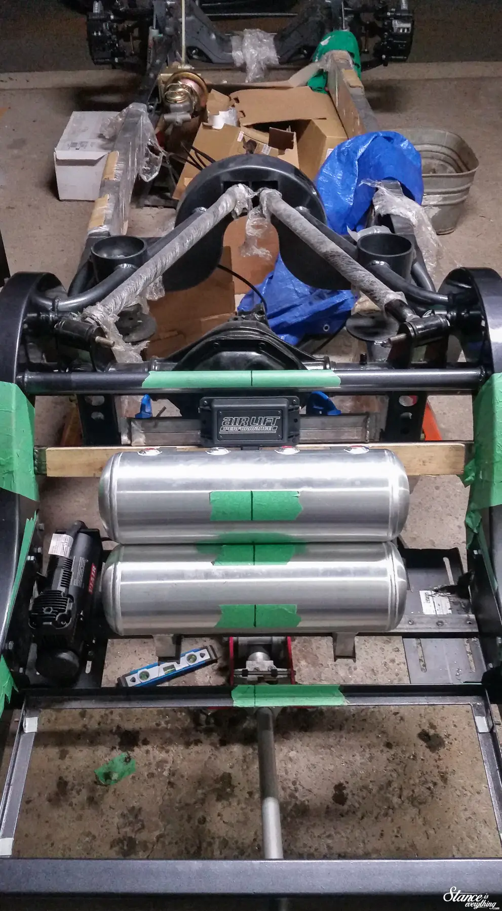
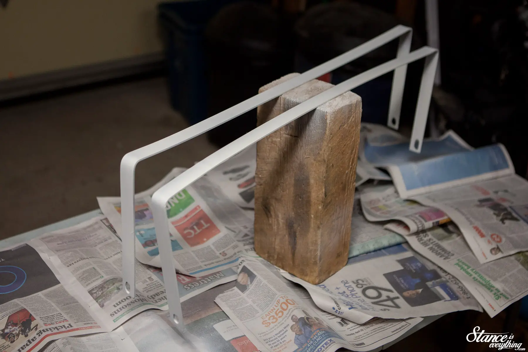
A quick solve for this was spacing the upper tank out from the cross member just enough to run the related plumbing and wiring. Above is the necessary spacing mocked up with wood and the aforementioned box steel/angle iron test piece.
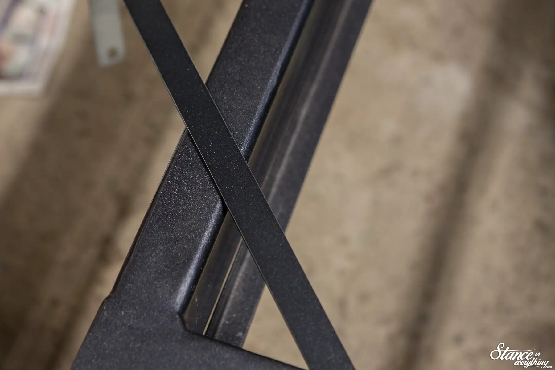
To make the manifold mount I bent up some flat stock to go around the box steel.
You’ll notice in the photo above I also ended up using the same material as the basis for the upper tank mount. I’ve actually used this steel a lot for various small brackets.
It bends easy, drills, easy, grinds easy, and thankfully welds quite easily.
Speaking of welding, while I wouldn’t say I’m a pro by any definition, my welds are starting to improve from earlier updates to the point where I don’t have to grind them down or worry about adequate penetration.
The learning curve has involved a lot of YouTube videos and an impressive pile of scrap metal.
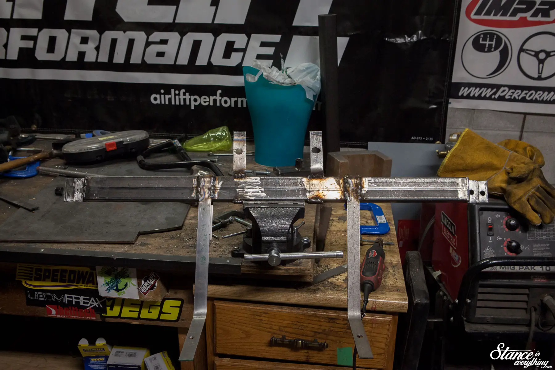
Above is the raw mount, all zapped together ready to go back on the chassis for more test fitting. Once back on the chassis I cut up some 1×1 tubing to space the tank out. Inside the 1×1 are bolts that I’ve welded in to mount the tank.
Unfortunately I manged to forget to take photos of that all coming together. Some nights I’d just get in the ‘zone’ and completely forget to pick up my camera.
I am happy to say however that everything went together quite well. The tanks ended up level, evenly spaced from each other, and on the center line.
However, just incase, all of the mounting holes, including those for the manifold, have been slightly slotted to allow for fine tuning as needed.
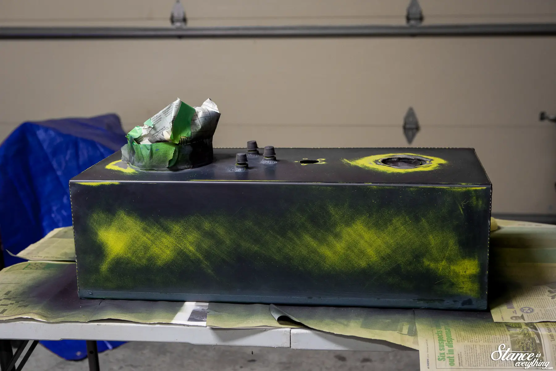
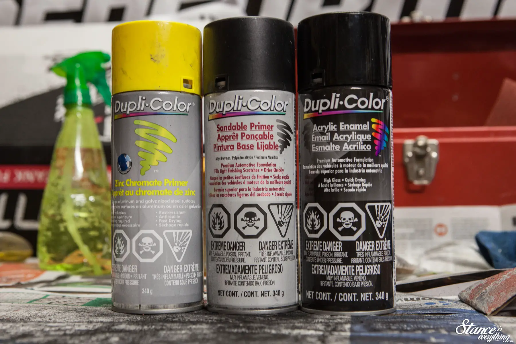
With everything settled on, and in position, I utilized a particularly warm November to shoot some color at the pieces I just made.
At this point you all are likely not going to believe me, but I don’t have a particular fetish for sanding and painting. It’s just a necessary part of the process behind building the truck I’ve got my heart set on.
I’m sure Car Quest is wondering what I’m doing with all these cans of paint.
I’ll have to swing by when the truck is complete.
 With a home for the air management decided it was time to move on to plumbing the chassis, with the first system being fueling.
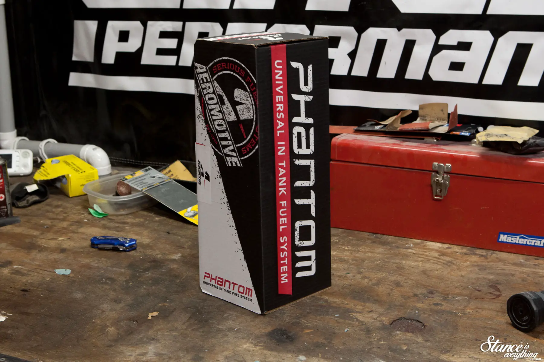
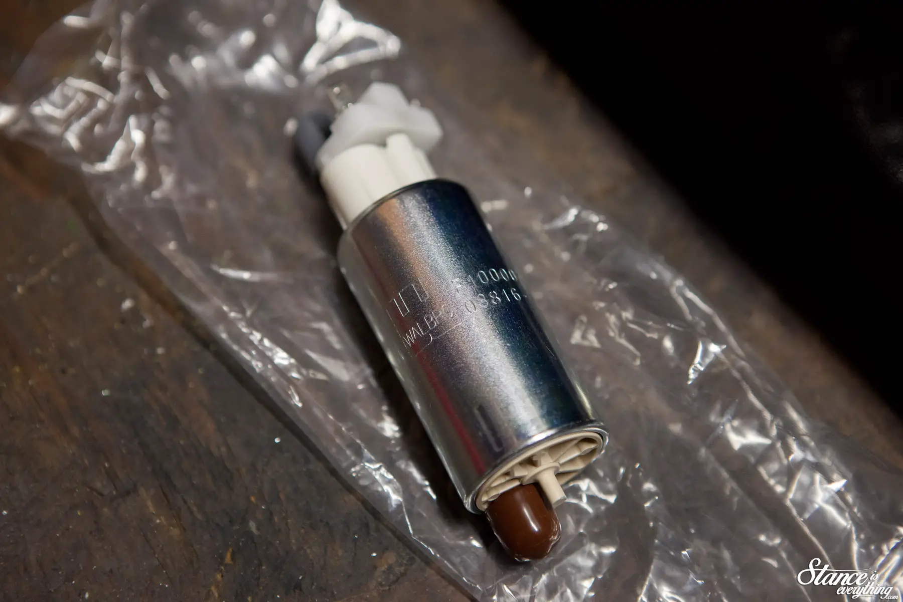
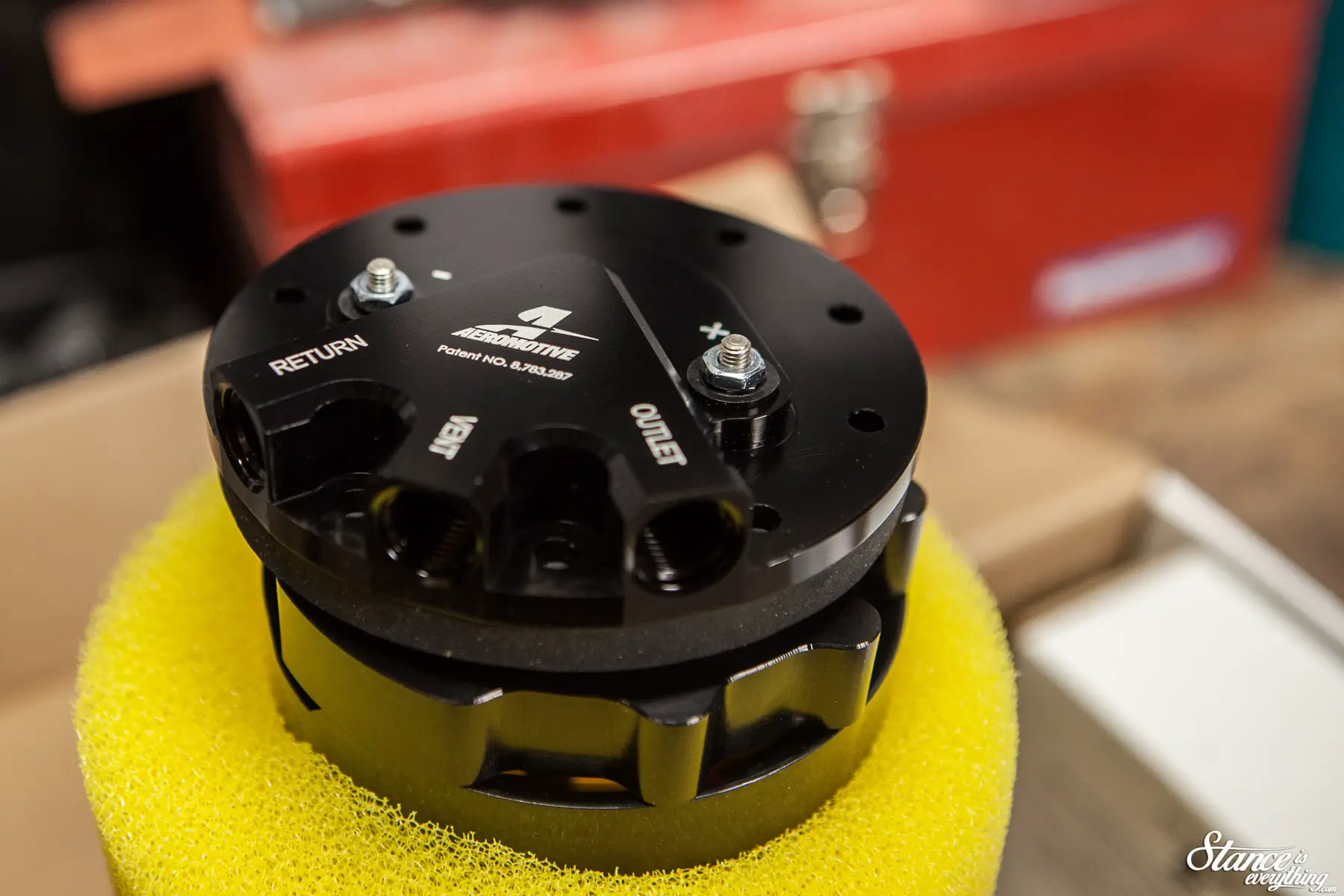
After consulting a few friends the Phantom Stealth drop in fuel system by Aeromotive seemed like the easiest route to take. Drill a few holes of various sizes and you’re pretty well done, and being a drop in I didn’t have to find any additonal space to mount it.
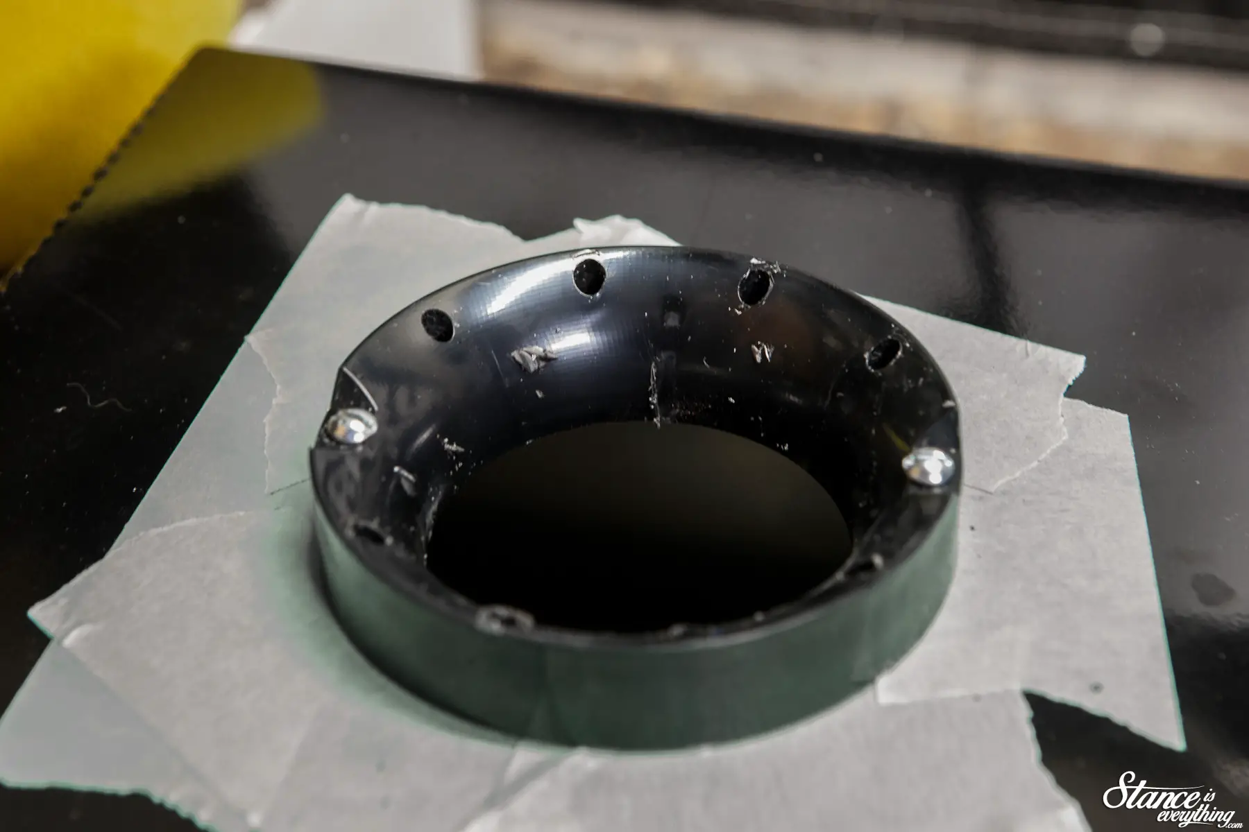
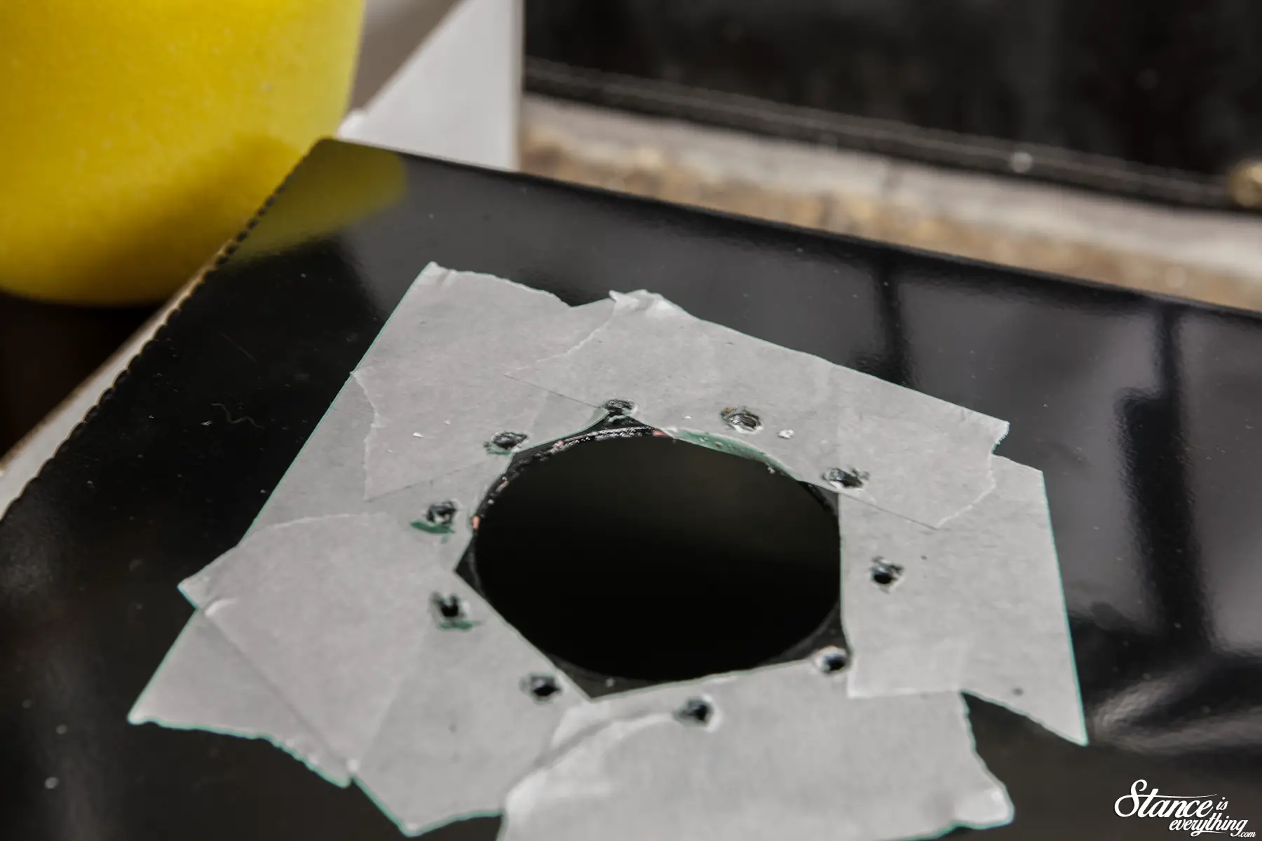
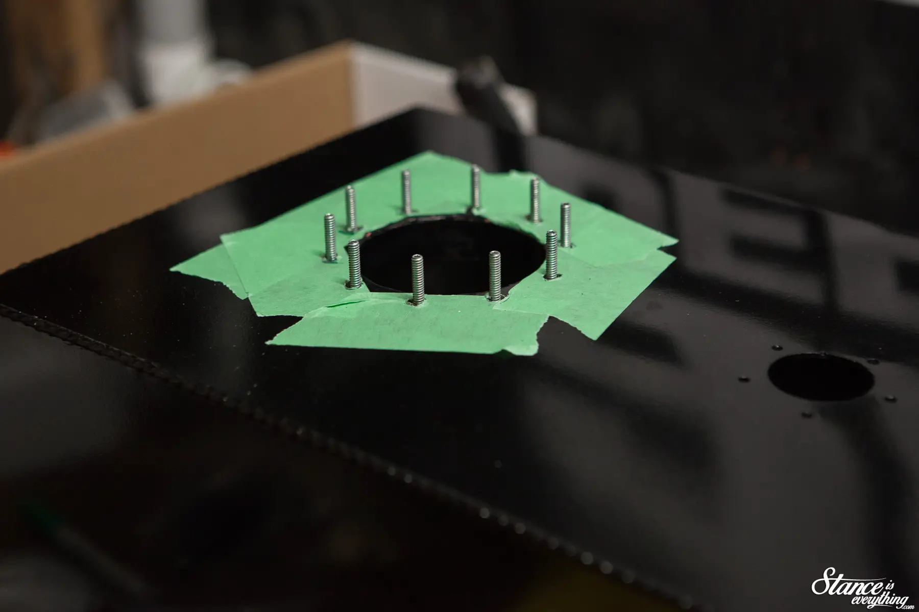
To begin the installation I selected a spot on the tank that looked symmetrical with everything I had already positioned. Then cordless drill made short work of cutting the hole and popping in the mounting holes.
You’ll notice in the process the tank color changes from raw to black, yep I painted that too.
 The top coat is unfortunately a little soft an easy to scuff/scratch, so don’t be surprised if eventually I end up with the black powder coated version of this same fuel cell.
RCI offers it, but for now I’ll just keep buffing out the black.
The Aeromotive install is actually pretty straight forward, the instructions are well written and if you can assemble a model kit, you can drop one of these in.
It’s a very nice piece of kit over all, and if you’re willing to spend a few extra dollars for some convenience and fueling piece of mind, I highly recommend it.
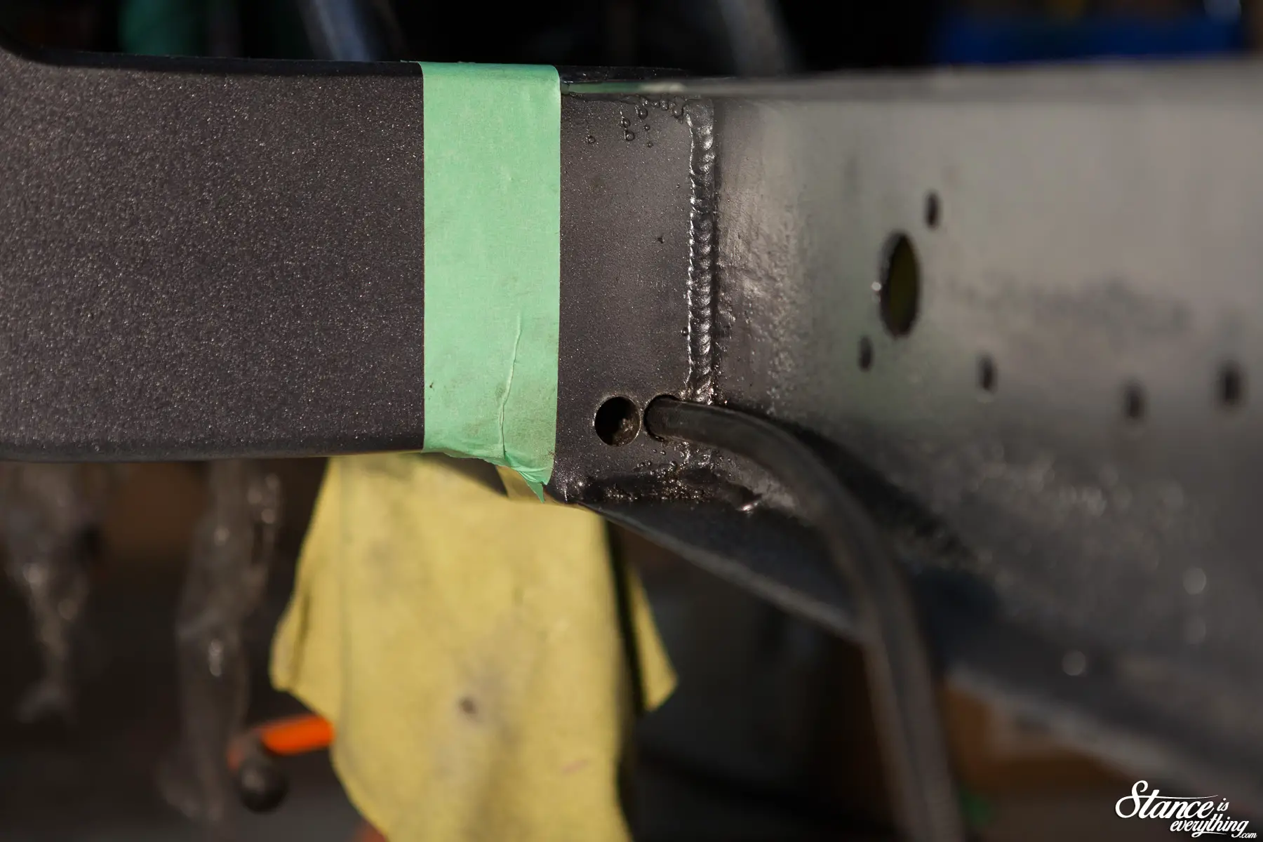
Once the pump was in the fuel cell it was time to consider fuel lines. It was here I discovered a slight problem, the safest (and cleanest) route from the back of the chassis to the front was straight through the frame.
This meant drilling a rather large hole through the cross member, then fishing the -6 Russel Pro Classic II fuel line through it, blind. Twice.
I filled the swear jar with this task.
To keep things nice and clean I opted to plumb it all with a combination of Russell and Vibrant -6 AN fittings depending on the union. I used Russell mostly but I preferred Vibrant’s 90 degree fittings.
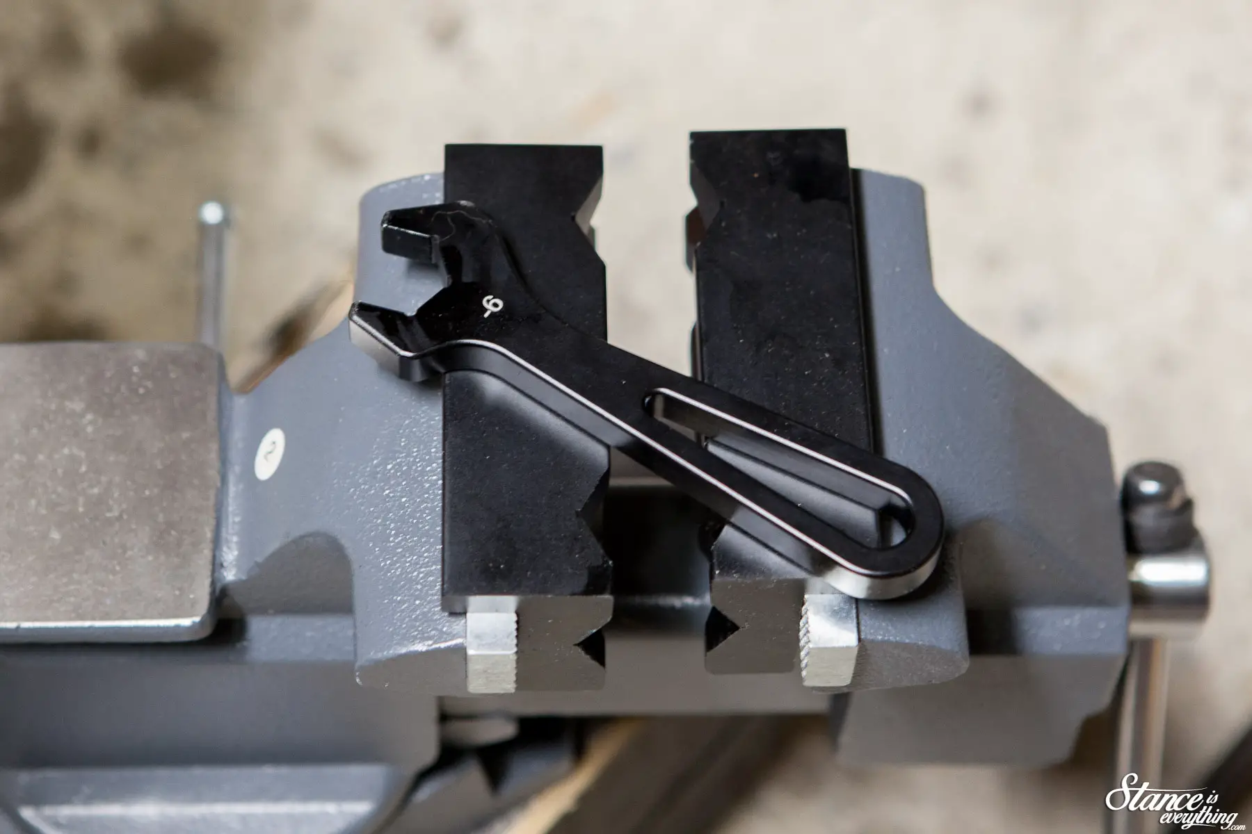
In an effort to minimize scratches I picked up purpose-built vice jaws and an AN wrench for this task.
If you’re ever thinking of assembling AN fittings without these I would advise against it.
It’s an additional expense for sure but it makes things considerably easier. Scratching AN fittings sucks, and with these tools I was able to keep most of my black fittings entirely black.
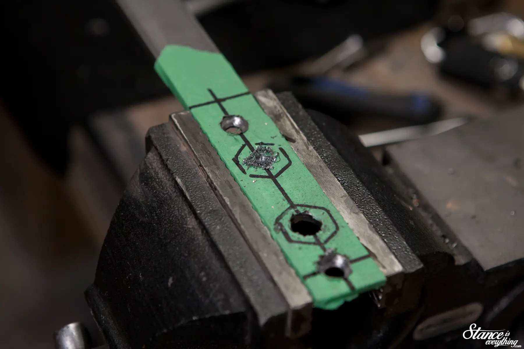
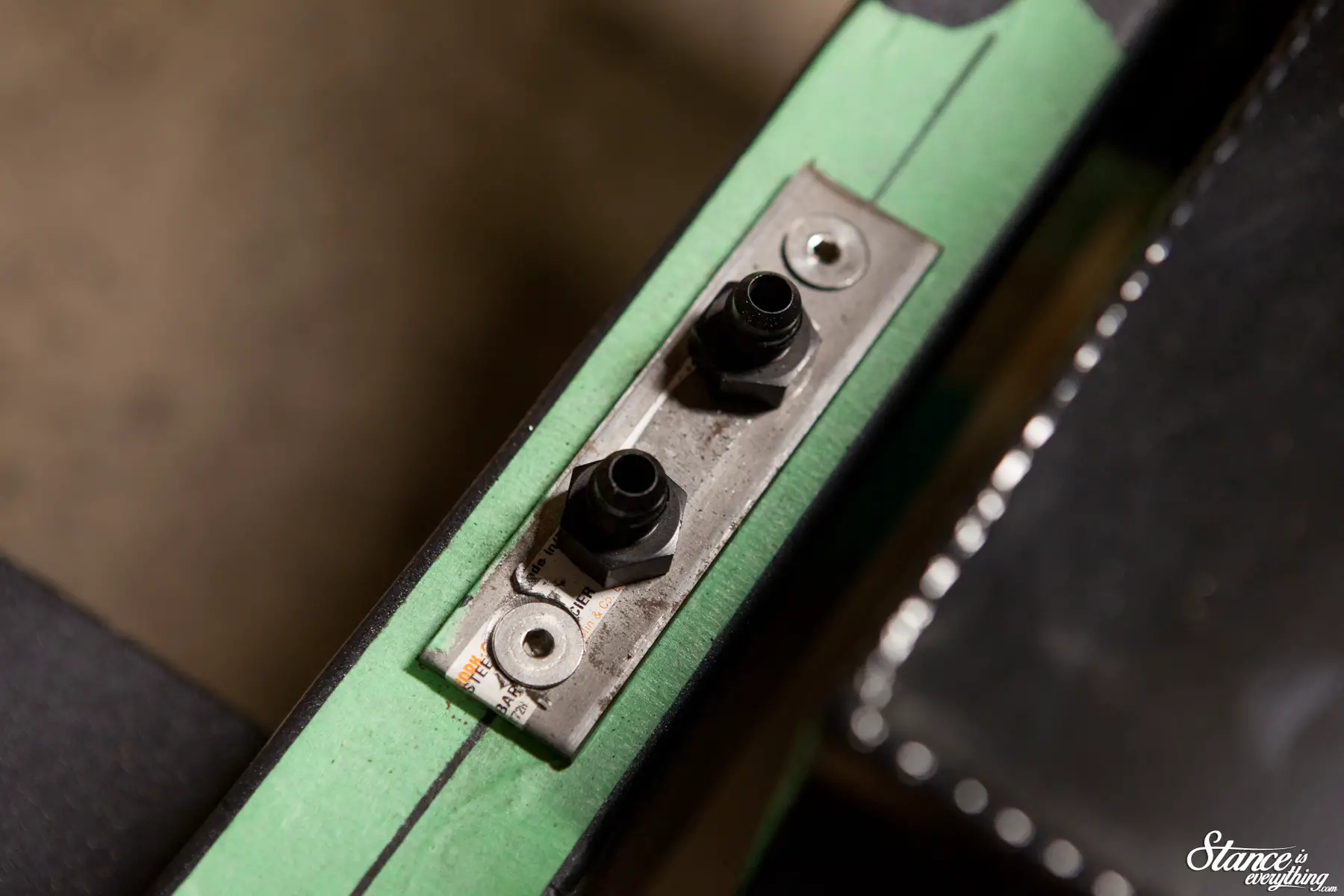
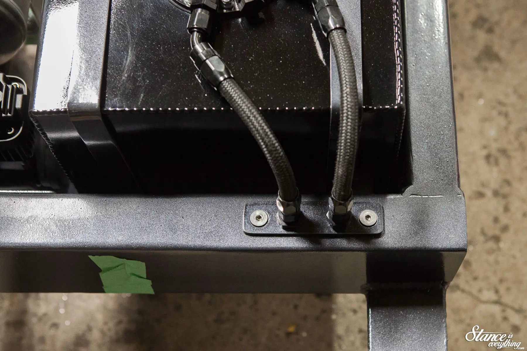
On the fuel tank end of the equation, instead of just passing the line through the frame I chose to make a bulk head plate
I could have probably just ran it straight through the frame, via a grommet but, to be honest I just wanted to try my hand at making bulkhead plate.
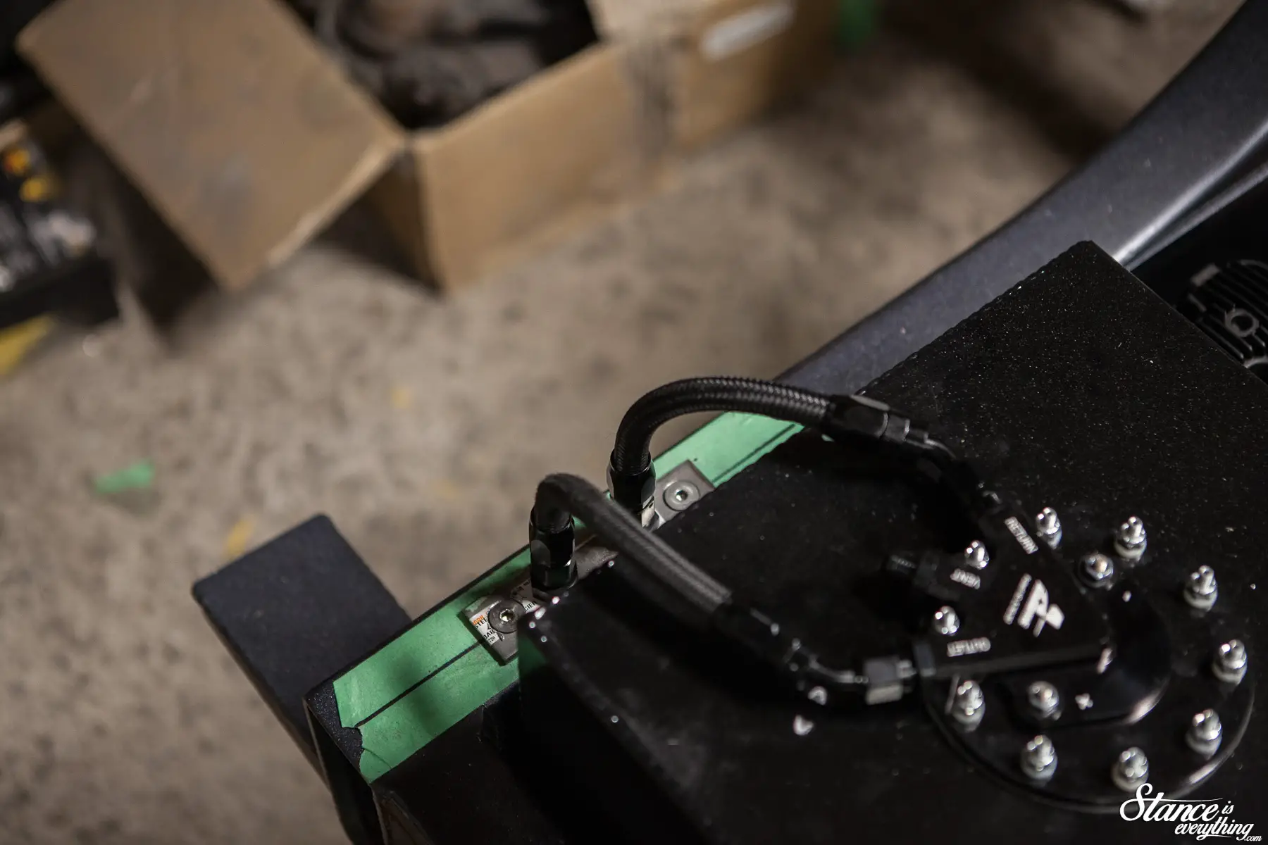
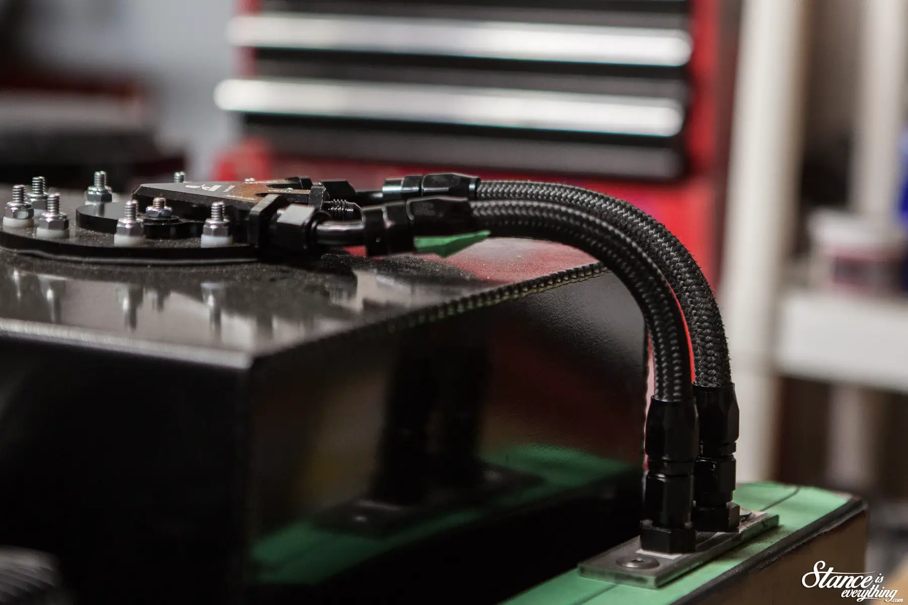
Two 45s at the fuel pump, and straight fittings at the end of the hose link everything together. For my first time running lines of this nature I am pretty happy with how it all turned out.
On the other end two straight, full flow fittings, go into my fuel filter/regulator. For those of you who know, this fuel filter is telling of my motor set up, but we will get to that in the next post.
I promise.
With the engine side done, and all the fittings on the fuel hoses, I dug out the fuel cell straps and shot them and the bulkhead plate with some color.
Once it was all dry I put it together and was finally able to see my vision for the back half start to come together.
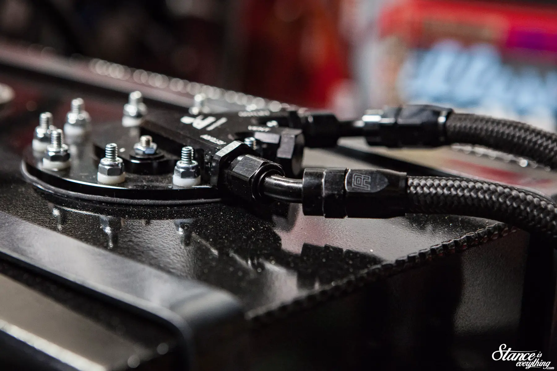 This is where taking the time to select all black fittings, rounding corners of my bulk head plate, painting and so forth really paid off. I couldn’t be more pleased with how it all looks buttoned up.
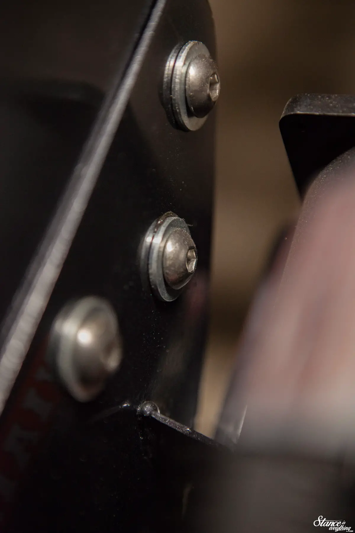
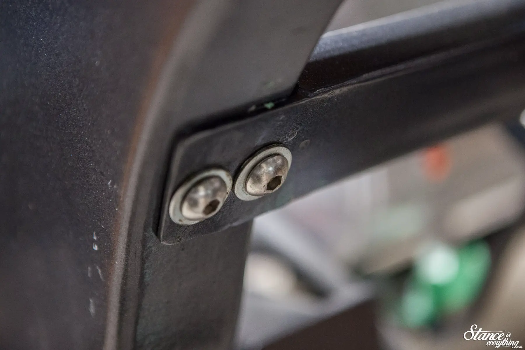
I even went so far as to switch out the bolts for button head allen fasteners. Another extra expense in an area few might notice (especially when I have a bed floor) but, I think it’s worth it don’t you?
You’ve probably noticed there’s a fair deal of dust and a couple scuffs on, well, everything. Chalk that up to my clumsiness and an unavoidably dusty work space.
Everything will all be cleaned up, touched up, and polished out by the time this truck sees the sun once more.
As soon as I drive this thing it will be covered in dust and scratches once more, but might as well start with the a clean slate right?
So, with that all said and done, here’s a parting shot of the back half of the chassis with most of the necessary components in place.
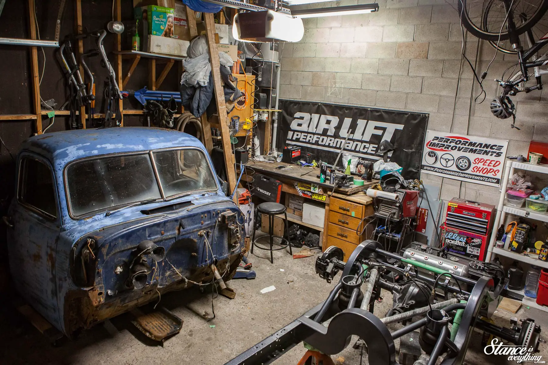
With the chassis inching closer to completion I opted to bring the body panels home from Taylor’d Customs for the winter in the event I need them before spring comes along.
It’s a little tight in the garage now, but being able to see the cab when I’m working makes everything seem that much more real. Special thanks to Nick, John, and Will for helping wrestle the works off the trailer and onto moving dollies.
Lots done, lots to do. Just have to keep pushing forward!
